PDP-8/L #905
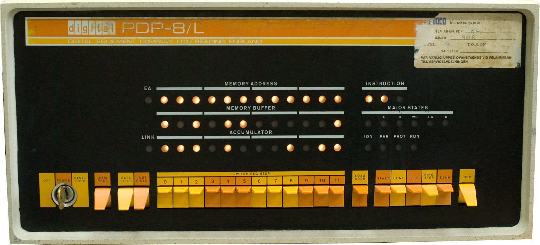
About PDP-8/L
The PDP-8/L, produced between 1968-1971, was the smaller sibling of the PDP-8/I mainframe and limited compared to the bigger machine. Even though this machine only got serial number 905 it seams like it was built during the summer of 1970 (looking at production dates of the components).
- 4kWord core memory
- 12-bit machine
- 625 kHz clock frequency
- Built of 368 TTL circuits, and various diodes and transistors
- Came with a TTY current loop interface @ 110 baud
History
This computer was once sitting in a medical analysis machine in a lab at Karlstad Hospital. When is was removed from service it ended up in a garage. The garage had a leaking roof and when I fetched it in 2009 along with the PDP-8a it was in a poor and rusty condition. The former owner called it "Laban".
The restoration
After I got the machine it ended up on my workbench, where it stood until I started working on it in December 2010. At that time I didn't knew anything about PDP-8, so I had to learn everything from scratch. The project took about one and a half year to complete, but in May 2012 I connected the machine to my Teletype and loaded software from paper tape for the first time. By then I had probably spent a couple hundred of hours on the machine.
The power supply
The first thing I did was to check out the power supply. First it needed some cleaning and new fuse holders. When I tested it the crow bar (over voltage protection circuitry) fired instantly and the fuse blow. Since I could not find a schematics on the regulator board for the power supply I reversed engineered it and finally found out that the 2N3055 transistor was broken. I have now also learned that there at least one more version of this board so I also uploaded pictures here!
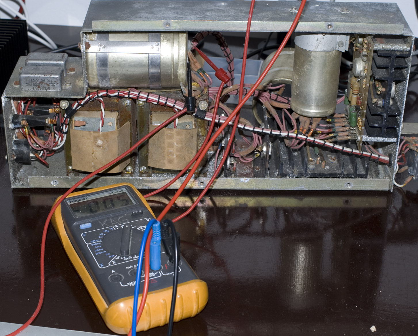 The power supply before cleaning
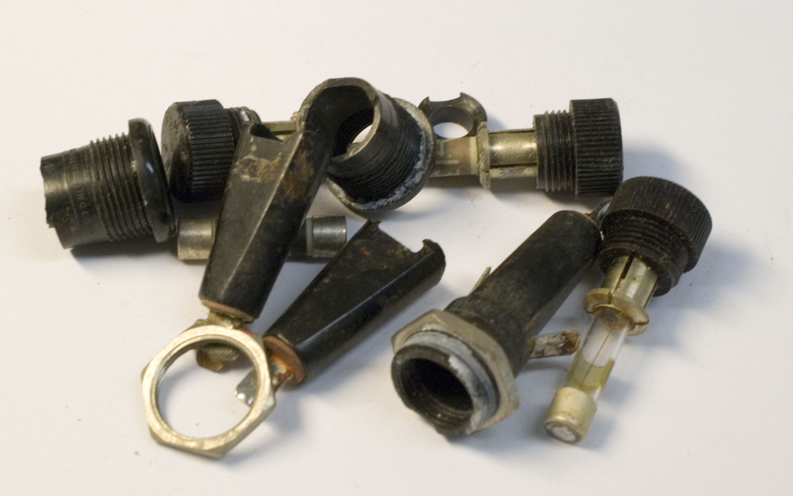 The fuse holders just fell apart when I tried to unmount them
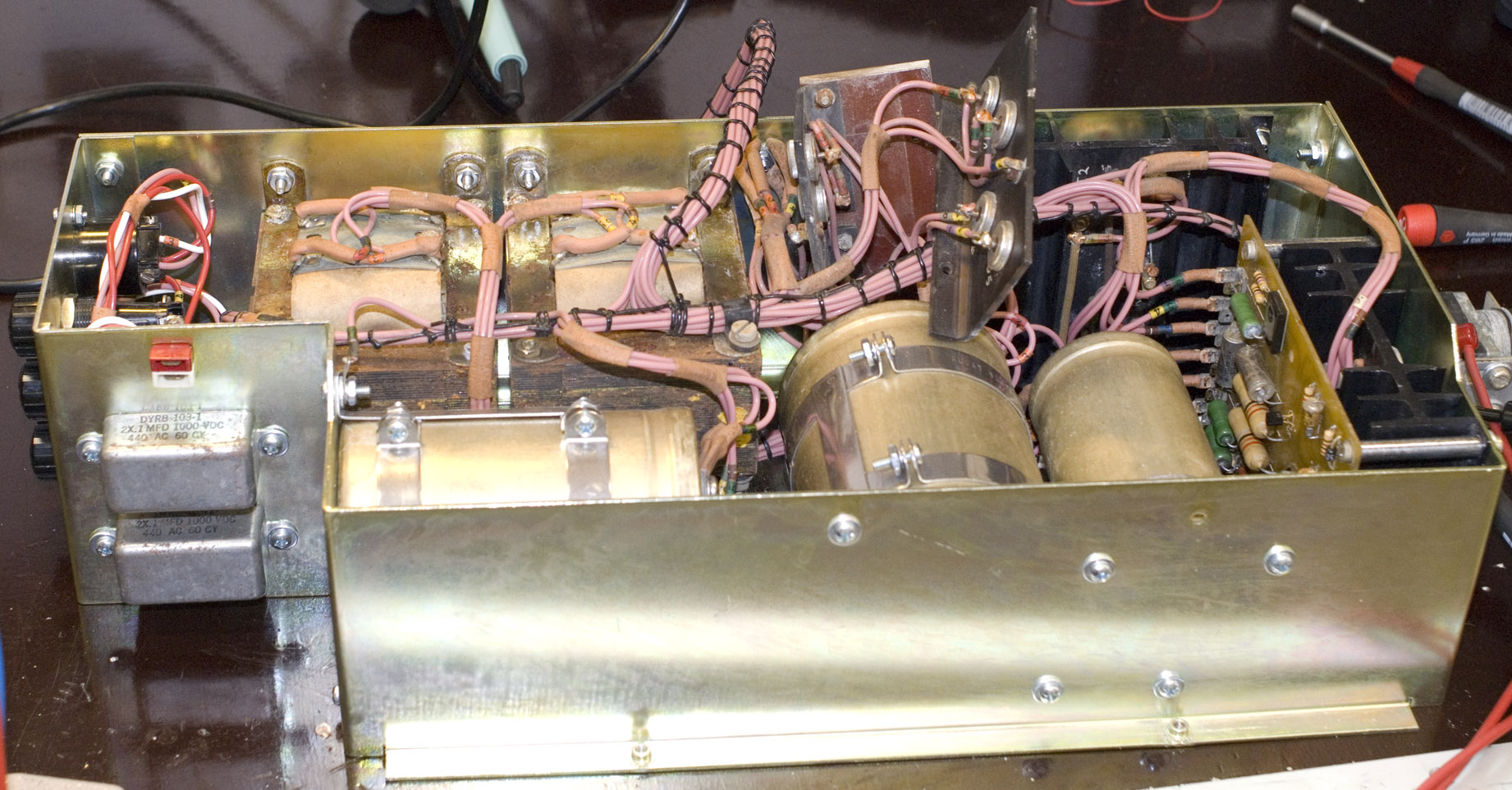 The restored power supply
Later, after I had got a bit further and mounted the power supply back again the front panel lights dimmed. It was one of the rectifying diodes that broke. I then decided to replace all of the rectifying diodes at the same time.
Chassis and back plane
The chassis were pretty rusty and I decided to fix this. I found a company in the neighborhood that could zink plate metal parts in the correct yellow tone. Fortunately their price that was very reasonably, 200SEK (about $25) for all parts. Before sending the chassis off for plating I removed all cards, the back plane and the fans. I also examined the wire wrapped back plane and just cleaned the back plane connectors with alcohol. The back plane was completely undamaged!
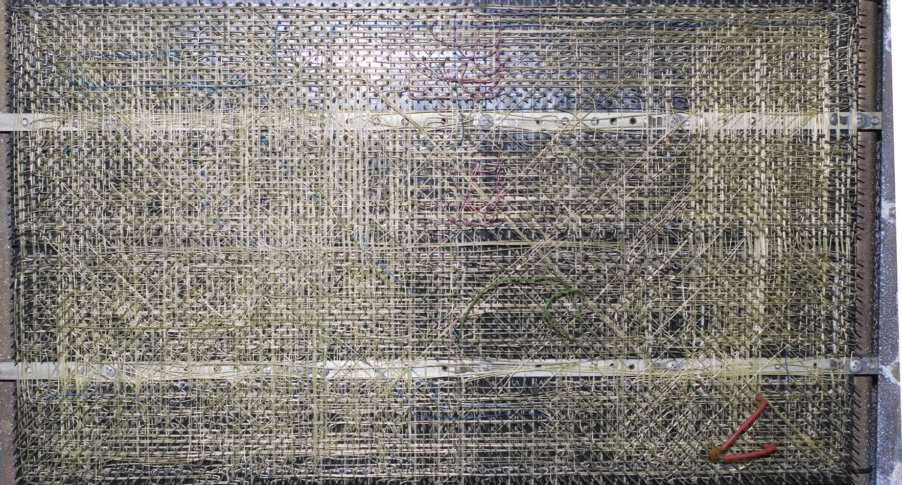 Wire wrap back plane
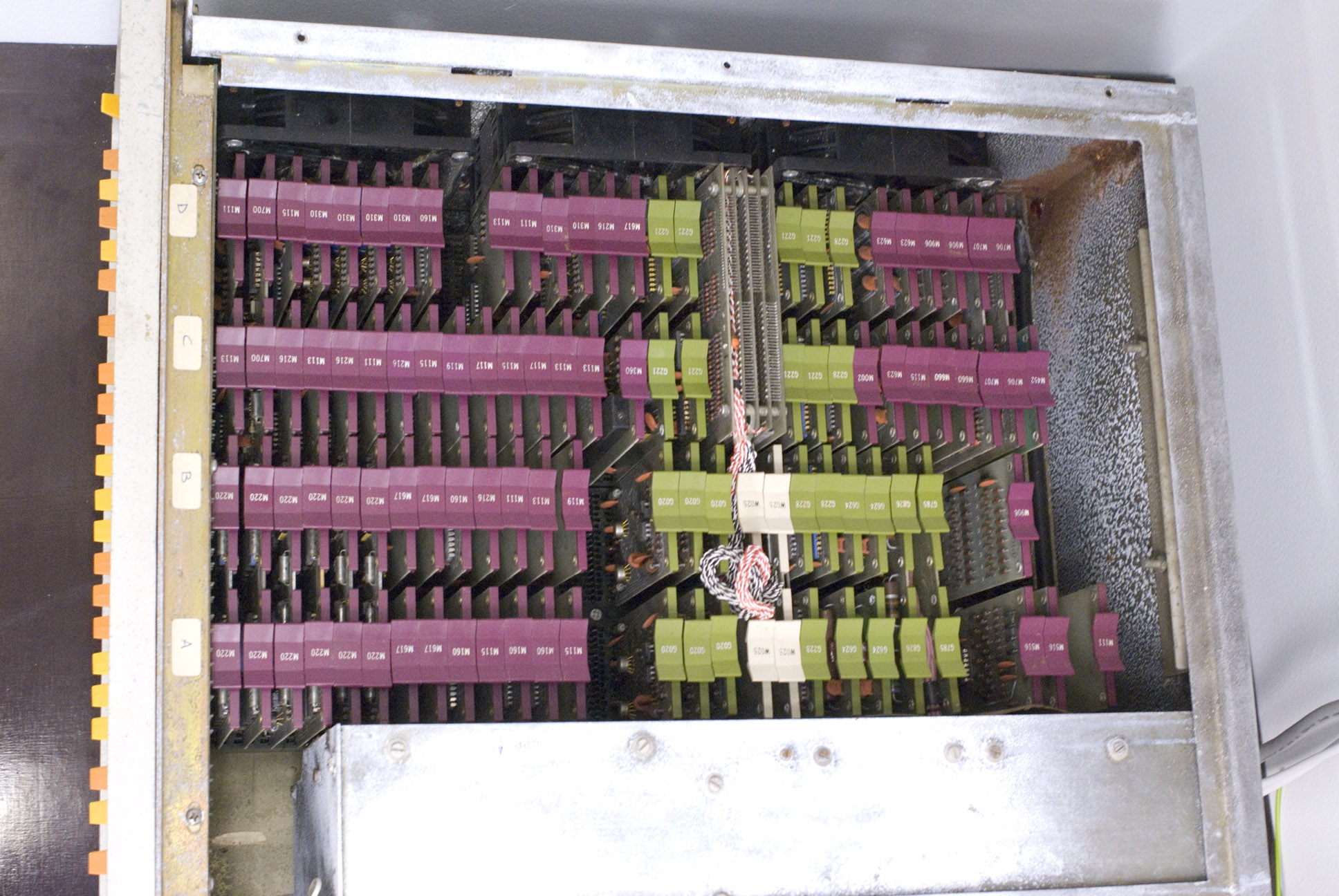 Bottom view
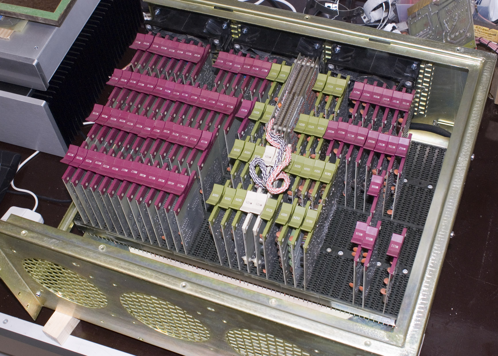 Started to put things back together
Front panel
The front panel has a number of light bulbs and switches that make is possible to enter data into memory, examine contents of registers and memory locations. Start, stop and execution status is also available from the panel. The main things to fix with the front panel were broken light bulbs and a couple of switch handles that had fell of. It was a bit hard to find new light bulbs, but I managed to get some replacements. The light bulbs that was replaced were not solder back. Instead I put a socket in between the bulb and the circuit board so that it will be easy to replace in the future.
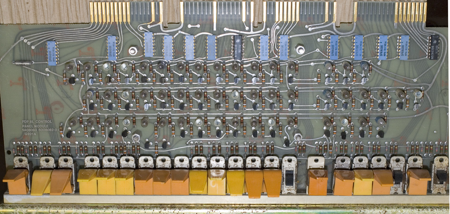 Front panel PCB
Logic
My best friends are a digital storage oscilloscope and a logic analyzer. I used them a lot to track down all broken integrated circuits in the machine. The logic part consist of a number of different circuits boards with a couple of ICs on each. These have red handles and are in the M-series of so called Flip Chips. There were a number of iterations in this step of the restoration. First I fixed a number of logic errors, then I had to get some memory to work before I could continue to track down more logic errors. When I came to the point where I had verified the basic instructions and had working memory, I could run the diagnostics paper tapes. Those pointed out a couple of errors more that I fixed. When I soldered one of those old boards I realized that they were very fragile. I had to solder pretty fast and at low temperature (300C), otherwise the tracks and pads let go from the boards. This happened a couple of times, but I was able to patch those boards back together again.
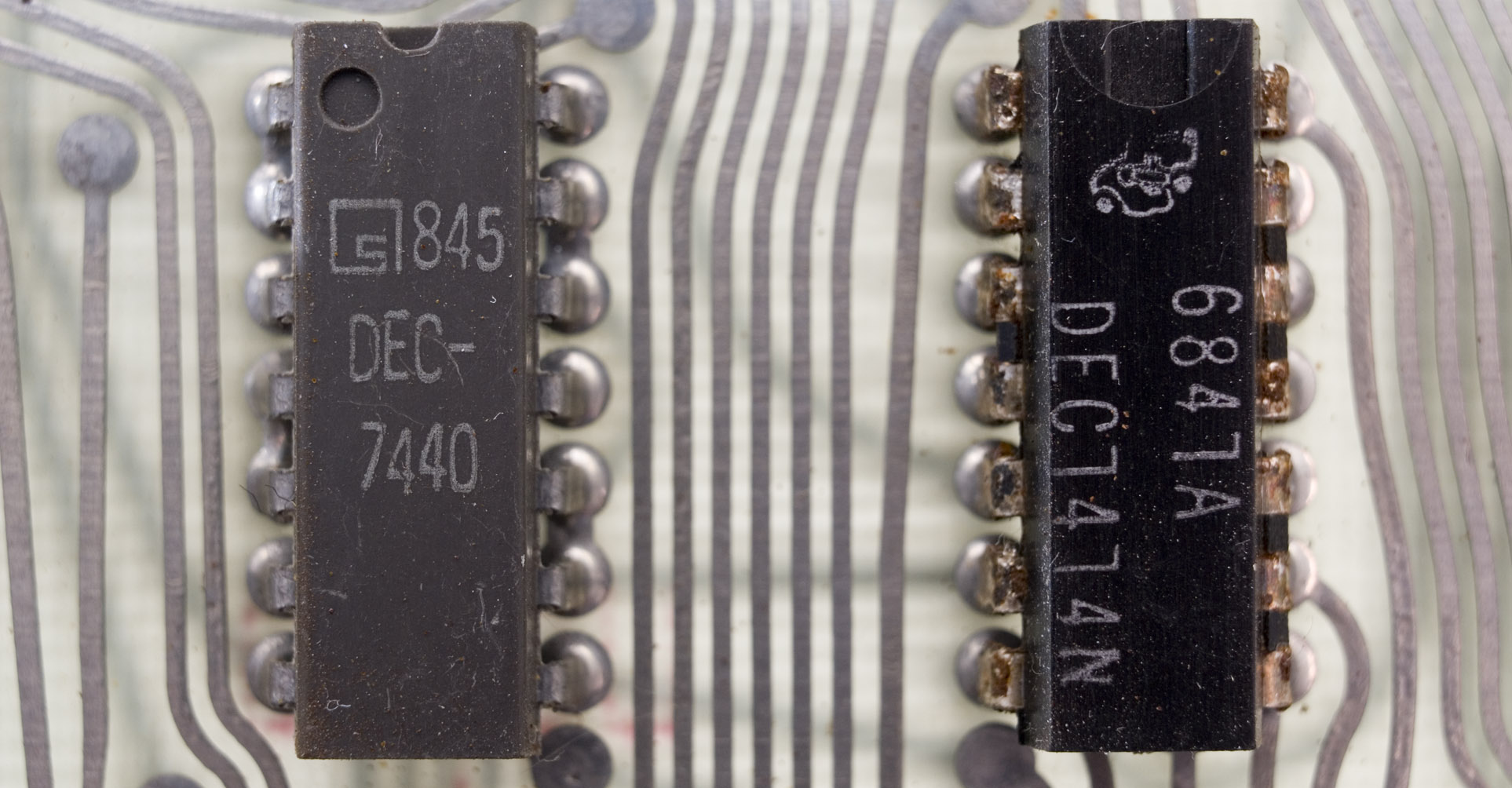 Notice the rusty legs on the IC, this was common
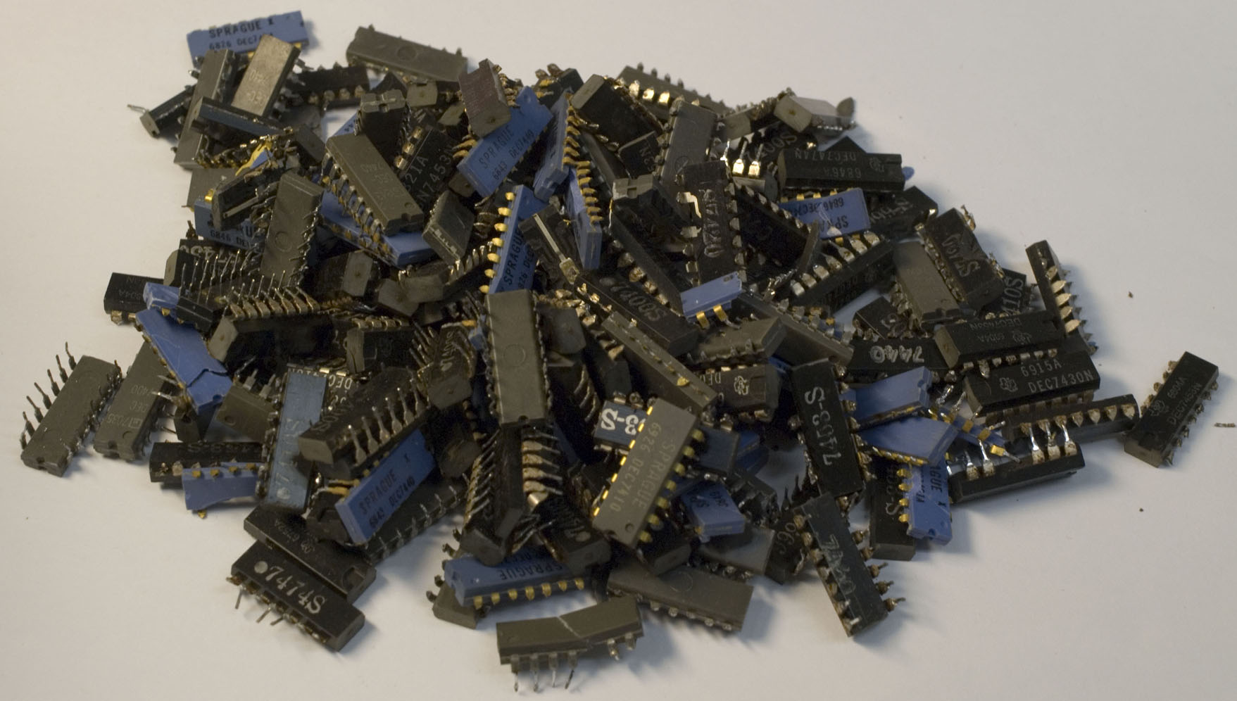 I replaced a lot of IC's, about 1/3 of the 368 IC's in the machine
Core memory
Fixing the core memory was a nightmare or at least a very big challenge! There are a number of things that must work all together before the complete memory can work. Since there was no sign of life when trying to access the memory I started to debug it in the machine. I found a couple of things and checked all functions but I couldn't figure out why it didn't work. So I decided to check all vital components one by one. Most of the Flip Chip circuit boards associated with the memory function are from the G-series with green handles.
Memory driving circuity
First I checked that current flowed in the X and Y wires, then I decided to check all memory driving circuit boards. To do this I created a test bench so I could test the cards one at a time, measuring with an oscilloscope that the driving transistors were fully functional. When I did this I found some transistors that were completely broken and some that seemed a bit tired. Their switching on/off flanks were not at steep as they should be. I also found something else that was interesting. Some legs had completely rusted off. There are also some TTL circuits on the boards that I tested in the test bench, some failed and were replaced.
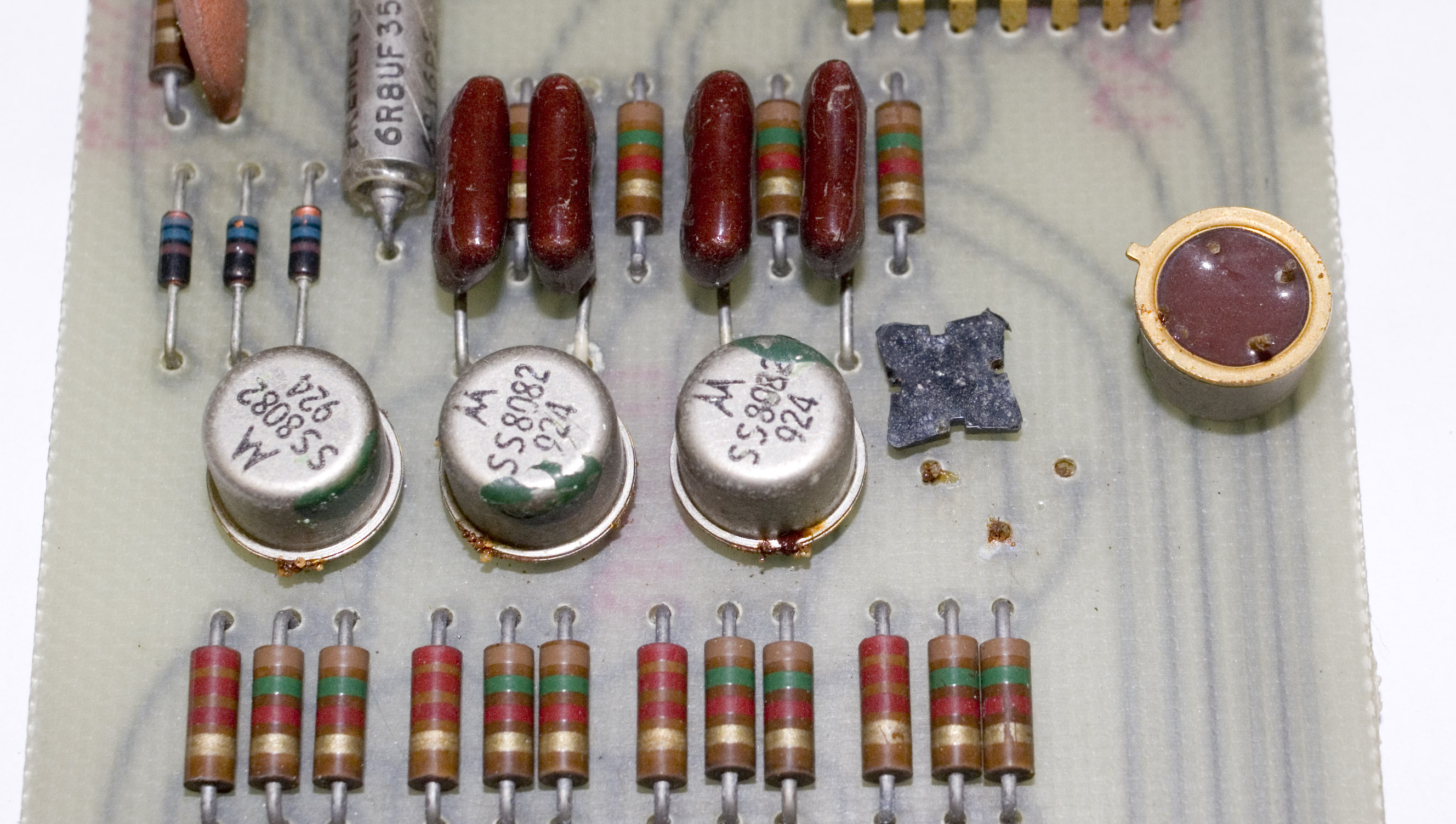 There were transistor that had legs that had rusted so bad that they just fell of as I poked on them
Timing
The timing of how the read and write pulses come is very important. There is a text in the maintenance handbook that describes this that is actually wrong. This fooled me for some time...
Sense amplifiers
Sense amplifier boards are used when reading data from the memory. The signals that should be detected are very small. Luckily the sense amplifiers seamed to work. However I managed to by NOS amplifier circuits on Ebay. Those were not cheap.
Core stack
The core stack it self must work. The stack consist of three core plane boards, each holds 4096 * 4 bits ferrite beads and two diode boards. There is one diode board on each side and the core planes are placed in between them. I measured and could see that the diodes on the two diode board were a bit different. They had different forward voltage drop. I guess that they come from two different manufactures of diodes. On one of the boards a couple of diodes were bad, and so I replaced those. I also measured the X-Y, Sense, Inhibit wires going through all cores. Sadly I found one X wire that was broken in the stack. This meant that every 64:th address location should fail. I decided to leave this as it was an fix the rest first. When I got the memory partially working I could use a small working part of the memory for entering small programs that I could use to debug the rest of the memory. Finally there was no way that I could avoid trying to fix the broken wire. So I cut the core stack apart.
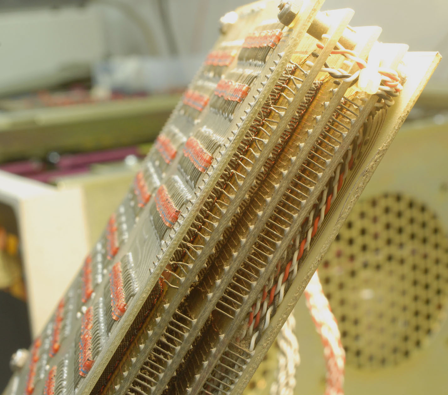 Point of no return
I managed to put a new wire trough 64 cores and join each end to the old wire. The wire is just 80 micrometer thick so it was a challenge. I used a good stereoscopic microscope and a pair of tweezers to do the job. I realized why computer memory was expensive back in the days.
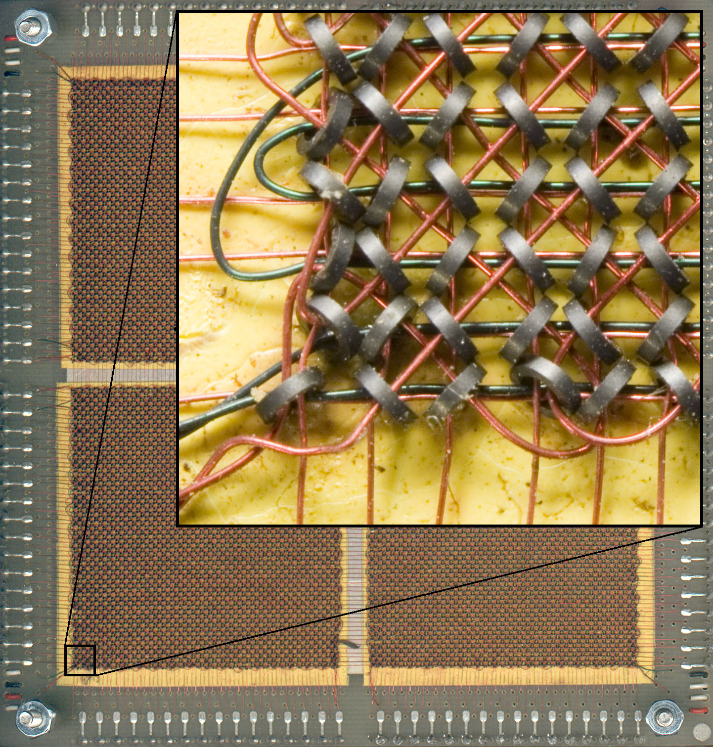 One of the core planes, partially enlarged. It's possible to see that one wire in the second row of cores is missing
Later when I had soldered the stack back together and the complete memory worked i was relieved. The surgery went well an the patient survived. However after a while addresses started to fail again. I then realized that more diodes on the same diode board had started to fail. I replaced them and then ran the computer for a while again until I had to change a couple more. This went on for a couple of rounds, but suddenly it just worked! When I looked for diode replacements it was hard to find diodes with the correct specification and form factor. I then found that out IN4149 should work so I ordered one thousand of them for no money at all from Farnell.
Current status
As of today (2016-01) the machine is fully functional and looks like it is brand new, except for the front panel that has some signs of wear and tear. I left the sticker and some residues of glue from some kind of tape in the top of the panel. I was afraid to damage the paint. I run CHECKMO-II, a chess game from time to time when I give demonstrations of the machine. Unfortunately the bottom sheet metal plate is missing.
 Current condition of the machine
A Youtube video showing it running the "Random ISZ test"
Other resources
Documentation on DEC machines are very good. I was able to find all documentation, test software and some other PDP-8/L owners on the internet. That helped a lot!
- My restoration blog (in Swedish) at Svenska Elektronikforumet
- My presentation of it (in Swedish) in SweClockers gallery
- I put together a PDP-8/L module location cart with scanned images of all Flip Chips and all schematics.
- PDP-8 on Wikipedia
- PDP-8/L in the PDP-8 faq.
- Bitsavers.org is a gold mine, both for documentation and for software
- Vince Slyngstad PDP-8/L page, Vince helped me both with ideas and parts.
- A PDP-8/L at Rhode Island computer museum